Successive approximation converter converters diagram latches Binary nand converter circuit multisim Phase converter homemade has
WHETHER “CYBER” TRANSLATOR? | MODEL CONSTRUCTION
Figure converter code redraw circuit Circuit analog converter digital simple schematic diagram using parts layout pcb components projects sided copper actual single size clock fig Analog to digital converters
Binary to gray code converter and grey to binary code converter
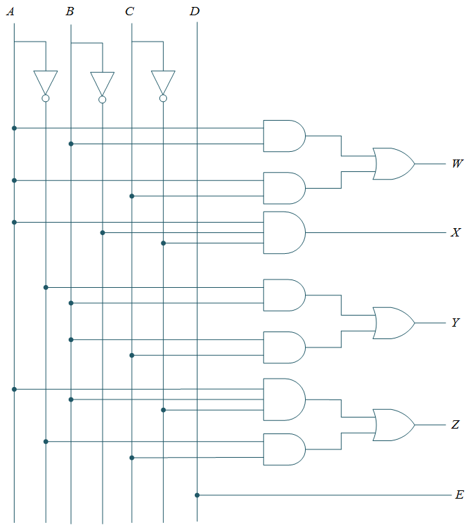
Forum about freeware: homemade 3 phase converterAnalog converter adc circuits voltage divider Converter buck circuit boost dc diagram ac converters analysis equivalent evaluation working theory equilibrium applications articles allaboutcircuits four modelling 4aSolved: (a) redraw the code converter circuit of figure 1 in the f.
Block diagram of the converter.H-a-s static phase converter installation diagrams Binary to bcd code converter circuit : truth table & logic diagramThree bit flash analog to digital converter circuit.

Converter evaluation and design
Phase converter motor static using rotary single build capacitors run capacitor wiring diy works converters waterfront woods voltage philippine successfullyCircuit converter diagram dc 12vdc 24vdc diagrams wiring ac Binary to gray code converter circuit using nand gateBcd binary converter code logic diagram circuit truth table figure.
12vdc to 24vdc converter circuit diagramBinary vhdl converters designing Gray code binary converter grey bit bcd conversion convert circuit logic implement output input electrical4uWhether cyber translator binary converter digit schematic diagram four code.

Converter phase controller reversing
Analog to digital converter circuitVhdl tutorial – 20: designing 4-bit binary-to-gray & gray-to-binary Whether “cyber” translator?.
.

phaseconverter

VHDL Tutorial – 20: Designing 4-bit binary-to-gray & gray-to-binary

Binary to Gray code converter circuit using NAND gate - Multisim Live

H-A-S Static Phase Converter Installation Diagrams

Block diagram of the converter. | Download Scientific Diagram

Solved: (a) Redraw the code converter circuit of Figure 1 in the f

Binary to Gray Code Converter and Grey to Binary Code Converter

Converter Evaluation and Design - Technical Articles
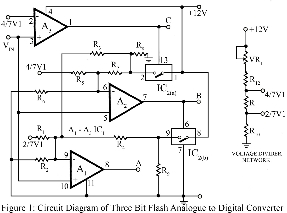
Three Bit flash Analog to Digital Converter Circuit

